

Material
Housing plastic.
Shaft stainless steel.
Connector thread brass.
Earthing terminal metal.
Shaft stainless steel.
Connector thread brass.
Earthing terminal metal.
Version
Nickel-plated brass.
1x M8 connector (A coded), 4-pole, 1x pin.
1x M8 connector (A coded), 4-pole, 1x pin.
Show more
Show less
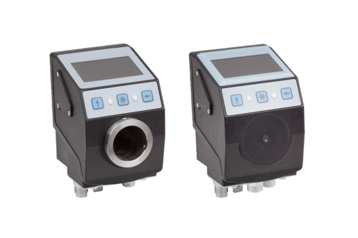
Position indicator, plastic, electronic IO link interface, Form A, with hollow shaft
from
€462.85
plus sales tax
plus shipping costs
Position indicator, plastic, electronic IO link interface, Form B, with magnetic sensing
from
€394.99
plus sales tax
plus shipping costs
Description
Material
Housing plastic.
Shaft stainless steel.
Connector thread brass.
Earthing terminal metal.
Shaft stainless steel.
Connector thread brass.
Earthing terminal metal.
Version
Nickel-plated brass.
1x M8 connector (A coded), 4-pole, 1x pin.
1x M8 connector (A coded), 4-pole, 1x pin.
Note
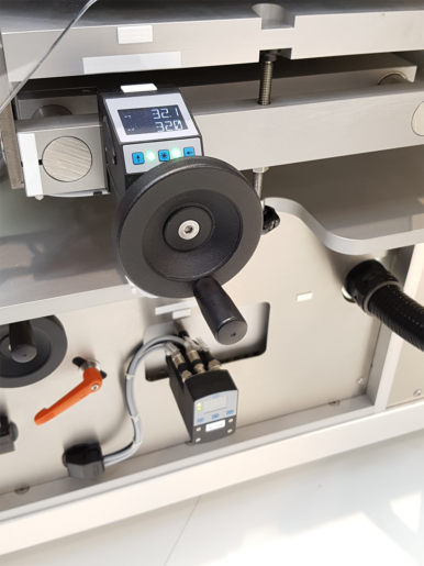
The IO link-enabled position indicators are used to check format adjustments, in order to effectively reduce set-up times and increase machine efficiency.
The two-line LCD display can display both the setpoint value and the actual value.
Two LEDs give the user visual signals indicating whether the setpoint and actual values match (LEDs lit green) or do not match (LEDs lit red). The LEDs also indicate to the user which direction of adjustment to apply in order to reach the desired position.
Position indicators K1657.1530 and K1657.1650 are linked to the application by a shaft. The position of the application is determined by a robust sensor system which uses magnetic scanning.
Position indicators K1657.1531 and K1657.1651 are mounted directly in the application. The position is determined by a magnetic sensor (K1658) and a magnetic tape (K1663). Suitable only for linear length measurement.
Technical Data
Position indicators K1657.1530 and K1657.1650:
Rotation speed: ≤500 rpm
Operating voltage: 24 V DC ±20 %
Current consumption: ~30 mA
Battery life: ~5 years
Resolution: 880 increments/rotation
Measurement range: ≤11914 rotations
Ambient temperature: 0 °C to +60 °C
Storage temperature: -20 °C to +80°C
Position indicators K1657.1531 and K1657.1651:
Operating voltage: 24 V DC ±20 %
Current consumption: ~30 mA
Battery life: ~5 years
Resolution: 0.01 mm (with magnetic sensor K1658)
System accuracy: ±35 µm (with magnetic sensor K1658)
Measurement range: ±655 m (with magnetic sensor K1658)
Ambient temperature: 0 °C to +60 °C
Storage temperature: -20 °C to +80°C
Scope of delivery
Position indicators
Assembly instructions
Assembly instructions
On request
Certificate of conformity.
Attention
These position indicators can be integrated only with a IO link communication system.
Drawing reference
1) Torque support
2) Grub screw M3 (2x 120°)
3) Min. space required to change battery without disassembling.
4) 2x M5/7 deep
5) Contact area
6) Earthing terminal for flat connector 6.3 or cable lug
7) IO link M8 connector (pin contact) metal connection thread
8) Sensor
2) Grub screw M3 (2x 120°)
3) Min. space required to change battery without disassembling.
4) 2x M5/7 deep
5) Contact area
6) Earthing terminal for flat connector 6.3 or cable lug
7) IO link M8 connector (pin contact) metal connection thread
8) Sensor
Accessory
Position indicators K1657.1530 and K1657.1650:
Reducing bush K0412.20**.
Position indicators K1657.1531 and K1657.1651:
Magnetic sensor K1658.
Magnetic tape K1663.
Reducing bush K0412.20**.
Position indicators K1657.1531 and K1657.1651:
Magnetic sensor K1658.
Magnetic tape K1663.
Discover our product range


